Rubber Slurry Pump
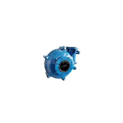
The Rubber Slurry Pump boasts wear-resistant rubber components that ensure extended operational life, even in the most challenging environments. Whether you're dealing with corrosive materials or tough mining applications, the Rubber Slurry Pump is designed to handle it all. Its versatility makes it a valuable asset across various industries.
Product Description
Crafted with wear-resistant rubber components, the Rubber Slurry Pump is designed to extend operational life while maintaining optimal performance. Its robust construction ensures seamless handling of abrasive materials, making it an ideal choice for industries such as mining, mineral processing, and dredging.
Experience reliable and consistent performance as the Rubber Slurry Pump excels in combating the challenges posed by abrasive slurries. Whether you're dealing with corrosive materials or tough mining applications, this pump's wear-resistant capabilities ensure sustained operation and reduced maintenance.
Overview:
HSR Rubber Slurry Pump is the similar structure with HS metal lined slurry pump. The main difference between HS and HSR is the material of wear parts. Rubber flow parts can be perfectly interchangeable with the metal parts. We provide various types of rubber wear-resistant parts for slurry pumps for customers to choose from. Clients can choose different material parts according to the slurry liquid conditions, such as DR26, DR55, DR33,DR08, DS42, DS10, DS12, DS01, DS02, DS21,DS31, DU03,DU27, DU38, etc. Rubber lined slurry pumps are more suitable in delivering high corrosive or abrasive slurries of small particle size without hard or sharp edges.
Discharge Size: 1" to 18"
Flow Rate: 3.6-4680 m3/h
Head: 7~50 m
Handing solids: 0-130mm
Slurry Concentration: 0%-70%
Pump casings Material: Ductile Cast Iron
Impeller, Liner, Throatbush: Natural Rubber; Synthetic Rubber
The wear parts Material Code: DR26, DR55, DR33,DR08, DS42, DS10, DS12, DS01, DS02, DS21,DS31, DU03,DU27, DU38 etc
Rubber Slurry Pump Detailed Features:
1. Well designed for interchangeable wet parts with metal lined slurry pump.
2. Casing - Casing halves of cast or ductile iron with external reinforcing ribs contain the wear liners and provide high operating pressure capabilities
3. Bearing assembly - A large diameter shaft with short overhang minimizes deflection and contributes to long bearing life. Only four through bolts are required to hold the cartridge type housing in the frame.
4. Pump frame - A rigid, one-piece casting cradles the “cartridge” shaft and bearing assembly. A minimal number of through bolts hold the pump casing to the frame. An easy means of external impeller adjustment is provided in a convenient position below the bearing housing.
5. Impeller - Front and rear shrouds have pump-out vanes. This design reduces recirculation and seal contamination, Elastomer impellers are made from rubber coated high tensile steel, Cast-in impeller threads require no impeller insert or nuts.
6. Liners - Rubber elastomer liners are interchangeable with hard metal. The elastomer liners are bolted, not bonded, to the outer casing. Elastomer seal rings back all liner joints.
7. Shaft seal - Packing seal,Centrifugal seal, and Mechanical seal.
8. Driving type - Flexible coupling, V-belt with pulleys, Gearbox, VFD, SCR control etc.
9. The discharge branch can be oriented to any eight positions at the interval of 45 degrees;
10. Easy to install and maintain in on-site application.
Benefits:
•The wear-resistant rubber components drastically reduce the need for frequent maintenance, saving you time and resources.
•The pump's robust design and wear-resistant capabilities ensure consistent and reliable performance, minimizing disruptions to your operations.
•With extended operational life and reduced downtime, the Rubber Slurry Pump contributes to a more cost-effective operation in the long run.
•Built to tackle the challenges of various industries, this pump is a versatile solution that adapts to your specific needs.
Rubber Pump Parameters
|
Model |
Max.Power (kw) |
Materials |
Clear water performance |
Impeller Vane No. |
|||||
|
Liner |
Impeller |
Capacity Q ( m3/h) |
Head H ( m) |
Speed n (rpm) |
Eff. η (%) |
NPSH (m) |
|||
|
1.5/1B-HSR |
15 |
RU |
RU |
10.8-25.2 |
7-52 |
1400-3400 |
35 |
2-4 |
3 |
|
2/1.5B-HSR |
15 |
RU |
RU |
25.2-54 |
5.5-41 |
1000-2600 |
50 |
3.5-8 |
3 |
|
3/2C-HSR |
30 |
RU |
RU |
36-75.6 |
13-39 |
1300-2100 |
55 |
2-4 |
5 |
|
4/3C-HSR |
30 |
RU |
RU |
79.2-180 |
5-34.5 |
800-1800 |
59 |
3-5 |
5 |
|
4/3D-HSR |
60 |
RU |
RU |
79.2-180 |
5-34.5 |
800-1800 |
59 |
3-5 |
5 |
|
6/4D-HSR |
60 |
RU |
RU |
144-324 |
12-45 |
800-1350 |
65 |
3-5 |
5 |
|
6/4E-HSR |
120 |
RU |
RU |
144-324 |
12-45 |
800-1350 |
65 |
3-5 |
5 |
|
8/6E-HSR |
120 |
RU |
RU |
324-720 |
7-49 |
400-1000 |
65 |
5-10 |
5 |
|
8/6R-HSR |
300 |
RU |
RU |
324-720 |
7-49 |
400-1000 |
65 |
5-10 |
5 |
|
10/8ST-HSR |
560 |
RU |
RU |
540-1188 |
12-50 |
400-750 |
75 |
4-12 |
5 |
|
10/8E-M |
120 |
RU |
RU |
540-1188 |
10-42 |
500-900 |
79 |
5-9 |
5 |
|
12/10F-M |
260 |
RU |
RU |
720-1620 |
7-45 |
300-650 |
80 |
2.5~7.5 |
5 |
|
12/10ST-HSR |
560 |
RU |
RU |
720-1620 |
7-45 |
300-650 |
80 |
2.5-7.5 |
5 |
|
14/12ST-HSR |
560 |
RU |
RU |
1152-2520 |
13-44 |
300-500 |
79 |
3-8 |
5 |
|
16/14ST-HSR |
560 |
RU |
RU |
1260-2880 |
12-42.5 |
250-450 |
80 |
4-8 |
5 |
|
20/18TU-HSR |
1200 |
RU |
RU |
1800-4680 |
13-44 |
200-350 |
80 |
2-7 |
5 |
Note:
1. "M" means high chrome alloy; "RU" means rubber(polymer)
2. Flow Rate range recommended : 50%Q≤Q≤110%Q

Rubber Slurry Pump Outline Dimensions

|
Pump model |
A |
B |
C |
D |
U |
E |
F |
G |
H |
J |
K |
L |
M |
N |
Shaft Key size (mm) |
Weight/kg |
|
|
Metal |
Rubber |
||||||||||||||||
|
1.5/1B-HS |
583 |
295 |
248 |
197 |
28 |
79 |
206 |
181 |
98 |
171 |
46 |
1 |
143 |
254 |
8*7 |
91 |
77 |
|
2/1.5B-HS |
592 |
295 |
248 |
197 |
28 |
79 |
217 |
205 |
114 |
184 |
33 |
/ |
143 |
254 |
8*7 |
104 |
118 |
|
3/2C-HS |
768 |
406 |
311 |
254 |
42 |
121 |
281 |
238 |
138 |
210 |
71 |
/ |
175 |
356 |
12*8 |
191 |
154 |
|
4/3C-HS |
843 |
406 |
311 |
254 |
42 |
121 |
354 |
292 |
149 |
262 |
24 |
/ |
175 |
356 |
12*8 |
263 |
236 |
|
4/3D-HS |
943 |
492 |
364 |
330 |
65 |
121 |
353 |
292 |
149 |
262 |
100 |
/ |
213 |
432 |
18*11 |
363 |
290 |
|
6/4D-HS |
1021 |
492 |
364 |
330 |
65 |
164 |
421 |
406 |
229 |
338 |
11 |
/ |
213 |
432 |
18*11 |
626 |
454 |
|
6/4E-HS |
1178 |
622 |
448 |
457 |
80 |
205 |
433 |
406 |
229 |
338 |
138 |
1 |
257 |
546 |
22*14 |
728 |
635 |
|
8/6E-HS |
1302 |
622 |
448 |
457 |
80 |
222 |
557 |
551 |
318 |
460 |
/ |
62 |
257 |
546 |
22*14 |
1473 |
982 |
|
8/6R-HS |
1360 |
680 |
590 |
350 |
85 |
222 |
554 |
551 |
318 |
460 |
/ |
170 |
490 |
560 |
28*16 |
1655 |
1164 |
|
10/8E-M |
1337 |
622 |
448 |
457 |
80 |
222 |
584 |
613 |
381 |
470 |
/ |
83 |
257 |
546 |
22*14 |
1625 |
1202 |
|
10/8ST-HS |
1748 |
1150 |
780 |
650 |
120 |
215 |
692 |
673 |
419 |
635 |
27 |
/ |
620 |
900 |
32*18 |
3750 |
3130 |
|
12/10ST-HS |
1816 |
1150 |
780 |
650 |
120 |
280 |
762 |
755 |
464 |
674 |
1 |
65 |
620 |
900 |
32*18 |
4318 |
3357 |
|
14/12ST-HS |
1873 |
1150 |
780 |
650 |
120 |
280 |
812 |
937 |
629 |
832 |
i |
224 |
620 |
900 |
32*18 |
6409 |
4672 |
|
16/14TU-HS |
2320 |
1460 |
1050 |
900 |
150 |
280 |
953 |
1048 |
660 |
889 |
/ |
84 |
860 |
1200 |
36*20 |
10000 |
7867 |
|
20/18TU-HS |
2475 |
1460 |
1050 |
900 |
150 |
350 |
1100 |
1414 |
940 |
1230 |
/ |
417 |
860 |
1200 |
36*20 |
17840 |
12750 |
Please contact us for the detailed outline drawings if needed.
Discover a new era of material transfer solutions with the Rubber Slurry Pump. Its wear-resistant design, robust construction, and exceptional performance make it a standout choice for industries requiring efficient handling of abrasive slurries. Elevate your operations, reduce maintenance hassles, and maximize productivity with the Rubber Slurry Pump – a testament to our dedication to providing cutting-edge solutions for your material handling needs.
